Lately I've been looking into adding infrared LEDs to my Raspberry Pi, as I just purchased the latest camera module v3, in its NoIR (no infrared filter) edition.
Basic knowledge required
Physics courses in high school took place like forever ago, I basically remembered nothing. So I had to dig it up a little bit and study basics again (Ohm's law for instance 😅).
Raspberry Pi
- It has 2 pins that output 5V, 2 pins that output 3.3V, a few "ground" pins, and the rest are GPIO pins, that can output 3.3V and are controllable.
- The Raspberry Pi can only supply a small current (about 60mA). The LEDs will want to draw more, and if allowed to they will burn out the Raspberry Pi. That's why we'll need to use a resistor. As a rule of thumb, any resistor equal or greater than 50Ω (Ohm) should suffice for one or more LEDs in series plugged on a 3.3V GPIO pin. More on that down below.
Multimeter
A tool to measure various things. The "A" (Ampere meter) plug acts as a closed circuit, so never put the test leads into the home sockets! The "V" (Voltmeter) plug acts as an open circuit.
LEDS
- The anode is the long leg of a LED, where you connect the +. The cathode is the - (on the side where the diode has a flat).
-
Extracts from stackoverflow.com:
The forward voltage is the voltage drop across the diode if the voltage at the anode is more positive than the voltage at the cathode (if you connect + to the anode).
You will be using this value to calculate the power dissipation of the diode and the voltage after the diode.
The reverse voltage is the voltage drop across the diode if the voltage at the cathode is more positive than the voltage at the anode (if you connect + to the cathode).
This is usually much higher than the forward voltage. As with forward voltage, a current will flow if the connected voltage exceeds this value. -
To paraphrase the last sentence, the forward voltage (tension de seuil in French) is the minimum amount of volts needed to light up a LED. If you connect the anode to the - and supply more volts than the reverse voltage, you'll burn the LED out.
-
"Forward voltage" and "voltage drop", two pieces of information usually found in LED specs, are almost interchangeable words. The "voltage drop" is the "forward voltage" at the specified current (amperage, intensité in French). If you increase the current (amperage), you'll increase the "voltage drop". That voltage drop varies depending on the current (amperage) and on the color of the LED, higher voltage = higher current (amperage). See the image further down below.
-
Other extracts from stackoverflow:
With an LED it's the amount of current flowing through it that determines how bright it is. Increasing the voltage increases the current, yes, but the region where that happens without the current getting too much is very small.
So we control the current instead of the voltage, and take the forward voltage as a fixed value. By either including a resistor in the circuit to fill the gap between the supply voltage and the forward voltage, limiting the current in the process [...]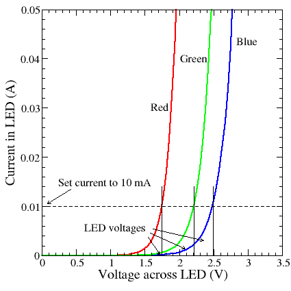
-
Extracts from LEDsupply.com:
Running a series circuit helps to provide the same amount of current to each LED. This means each LED in the circuit will be the same brightness and will not allow a single LED to hog more current than another.
“The total voltage of the circuit is the sum of the voltages across each LED”. This means you have to supply, at minimum, the sum of the forward voltages of each LED.So if my series circuit, connected to the GPIO pins of my Raspberry Pi, supplies 3.3V, and I plug in 2 LEDS whose forward voltage is 1.5V, there will be 3V "consummed" and 0.3V "remaining".
-
Extracts from LearningaboutElectronics.com:
The Continuous Forward Current specification of an LED serves to tell you the maximum current that an LED can be fed continuously without being damaged or destroyed.
The Peak Forward Current, IF(peak), specification of an LED serves to tell you the maximum current that an LED can be fed without being damaged or destroyed.
Resistor needed
As seen above, with 2 LEDs in series, each with a forward voltage of 1.5V for 20mA, plugged on a GPIO pin supplying 3.3V, we need a resistor as follow:
I = V/R
IF = (VS - VF) / R
# IF = forward current, VS = supplied voltage, VF = forward voltage
0.020 = (3.3 - 1.5 - 1.5) / R
R = (3.3 - 1.5 - 1.5) / 0.020 = 15 Ω
Note that, if we shift our target amps from 20 to say 40mA to allow the LEDs to draw more current, their forward voltage will increase. Check the specs to know how much. Never aim higher than 60mA, as it's the maximum the Raspberry Pi can deliver.
Now if we have just one LED and aim for maximum current (60mA):
R = (3.3 - 1.5) / 0.060 = 30 Ω
That's why in the beginning of the article I wrote that 50 Ω is safe for almost all scenarios. 1.5V is among the lowest voltage values drawn by LEDs, since infrared LEDs are those that need the least. For a different color (blue for instance), the computation would most likely look like this, depending on the actual specs of course:
R = (3.3 - 2.5) / 0.060 = 13.3 Ω
What I ended up doing
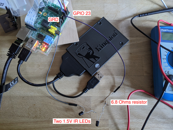
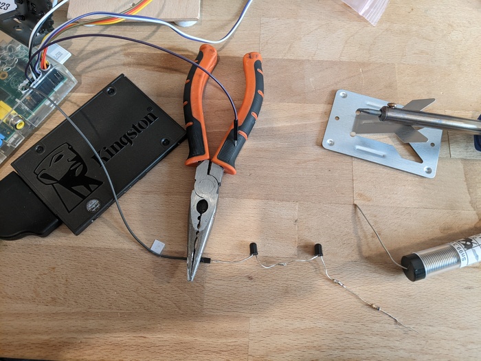
In the end, I bought two 1.5V 5mm IR LEDs and a 6.8 Ohm resistor, that I soldered all together. The result is pretty nice, and it's working like a charm. By connecting it to a regular GPIO pin, I can programmatically turn it on and off.
Note that the LEDs I bought have a wavelength of 940 nm. I believe the camera with embedded LEDs I had before was 850 nm. 850 nm is visible by the human eye (dim red) while 940 is not at all. 940 also appears less bright on video than 850, from my experience, in pitch dark.